Steve Bomford is a Training and Application Support Manager with Oerlikon Metco in the UK. Steve is passionate about thermal spray and have over the years in many different positions gathered an extensive amount of knowledge abou thermal spray.

We have a part to spray. It’s there waiting after being masked and blasted (covered in the last two articles), so we’d better move on. We are under time pressure for many reasons. One, in particular, is the oxidation rate of the substrate. Each metallic substrate has an oxidation potential, some greater than others. What we don’t want is for a poorly adhered oxide film to effect the bond strength of our coating waiting to be applied. Basically, it’s best practice to spray as soon as possible after activation. If in doubt, use the 2 hour rule: The maximum time period after blasting before we need to start spraying without at least a “freshen up” of the activated surface.
What should we have thought about well in advance of getting our part ready to spray? The following is a starting list which we will cover in this article:
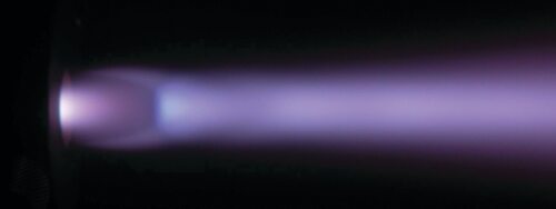
Why go to all that effort of moving the gun and/or the component? Of course, we want to make sure we deposit the coating where we want it, but we also need to produce an even coating thickness as well as a controlled thickness per pass. If we just held the gun stationary (and you can test this sometime if you are keen), then the coating will build up over a short time in the form of a sharp point. This is primarily due to the fact that the most efficient heat transfer and optimum particle velocity tend to be in the center of the spray stream (see Figure 1).

Figure 1: Cross-section of typical spray plume showing deposition profile.
It’s important to note that the center of the spray stream may not necessarily be the center of the “flame”. For single external injection systems, the powder may well drop through the flame and therefore the deposition profile will be off centerline. This will therefore affect the position in which the coating is deposited (this will have to be considered in the manipulation program).
Figure 2 shows the output from a typical spray diagnostic device (in this case Accuraspray-4.0). As can be seen with this material, sprayed with the F4-MB Air Plasma Spray gun, a typical powder drop through of approximately 5° is noted (also note the spray profile shape to the right of the image). In order to produce our uniformly deposited coating, we need to even out the spray profile as best as possible during the relative motion of the gun to the part sprayed. Effectively, this means controlling the step height of the gun as it builds up the coating. The step height required is proportional to the size of the spray spot (i.e., the flame width with material flowing).
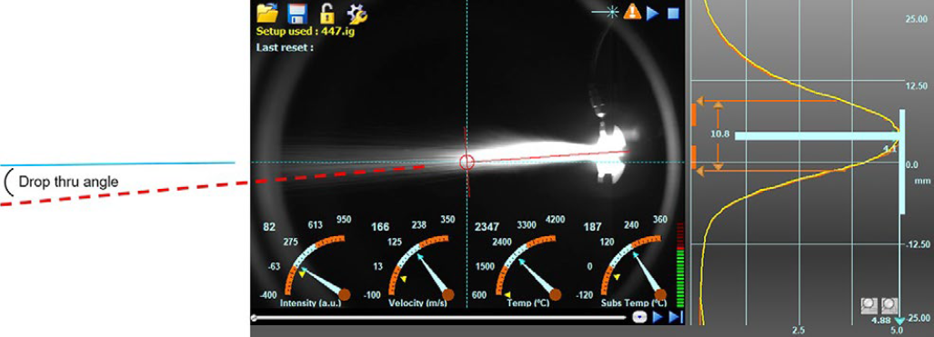
Figure 2: Spray diagnostic view of F4-MB spraying Metco 447NS.
In order to control our thickness per pass (over the component) we need to be mindful of the surface speed employed as the gun moves over the surface of the part being coated (or occasionally vice versa). For any given process and fixed spray gun parameter set, there are general starting guidelines for the step height and surface speed employed. Starting values are given in the table below for most thermal spray processes when spraying both flat (weave/ladder pattern) and cylindrical (rotation) geometries.
Process |
Flat Component |
Cylindrical Component |
||
|---|---|---|---|---|
Minimum Surface Speed |
Step Height |
Minimum Surface Speed |
Step Height |
|
| Air Plasma Spray | 60 | 5 | 75 | 5 |
| HVOF-GF | 60 | 4 | 75 | 4 |
| HVOF-LF | 60 | 8 | 75 | 8 |
| Electric Arc Wire Spray | 45 | 15 | 45 | 15 |
| Combustion Powder Spray | 45 | 10 | 45 | 10 |
| Combustion Wire Spray | 45 | 15 | 45 | 15 |
So, for a cylindrical component, we would usually rotate the part as the gun traverses over it (see Figure 4). In order to produce our nice, even coating (as an example, for Air Plasma Spray) we would traverse over the part moving the gun at a pitch of 5 mm (LST) every time the component rotated one revolution.
In order to produce our controlled thickness per pass, we would need to rotate the part at a surface speed of 75 m/min (VR1). To achieve our desired coating thickness, multiple passes will be required. If you don’t stick to these guidelines, Figure 5 shows an example of what can happen. In this case, a “barber’s pole” effect has been produced on the shaft when the gun has moved over the surface at too high a surface speed while still using the guideline step height (in this case 4 times the surface speed suggested).
Surface speed may well be a constant for the spraying process used, but that doesn’t help me work out my rotational speed (especially if I’ve got lots of differing diameter parts to spray). Fortunately, there is an answer at hand! Utilizing the following formulas will provide a matched surface and step height independent of part diameter.

Figure 4: Surface speed and step height settings for a simple cylinder.
Figure 5: A real-life barber’s pole and the surface speed effect that takes it’s name.
Where:
Where:
As an example, if we take a 0.5 m diameter part which we want to atmospheric plasma spray, then our starting point surface speed should be 75 m/min with a suggested step height of 5 mm (see Figure 3). To set up the manipulation to provide a controlled deposition process, we should rotate the part at: 75 ÷ (π · 0.5) ≅ 48 RPM, and traverse the gun over the surface at: 48 · (5 ÷ 60) = 4 mm/s.
If number crunching is not your favorite pastime, then these results can be plotted out in the form of a chart and set out somewhere near the booth. This will act as a ready reckoner dependent on your required level of process control.
If you have a flat component to process, then the surface speed needs to be provided by the motion of the gun over the part, with the step height and change of direction being clear of the surface being coated. This is typically achieved using a ladder pattern something like that shown in Figure 6. If these parts were being sprayed using HVOF-GF, then guidelines suggest that VTR would be minimum of 75 m/min with LST set at 4mm.
Both the rotation and weave patterns described here are an ideal starting point for simple geometries. Of course, once your first pass has been completed (under controlled manipulation conditions), then you are able to build up the coating using a series of passes until final thickness is achieved. By managing the thickness per pass (in combination with gun spray parameters) we can control the overall stress in the coating thus optimizing coating adhesive and cohesive strength.
We still have to be aware, however, that thickness limitations exist for all coatings. The thickness limit is effectively when the internal stress level in the coating is higher than the mechanical bond strength to the substrate i.e. the coating comes off!
Thickness limits are often application specific, but as a general rule, the more brittle and the more highly stressed the coating material, the lower the thickness limit. Intrinsically linked to the manipulation program is the setting of spray distance from the gun to the component. As this can also have a profound influence on the coating properties and therefore the spray parameters used.
Figure 6: Simple weave patter schematic.
Another critical factor when setting up for spraying is that of temperature control. Heat transfer to the part being coated needs to be controlled in a fashion that does not allow the part to continually increase in temperature until it reaches a point where its material properties are compromised. A balance is therefore necessary between heat in and heat removed.
The optimum process temperature for any application will depend on many factors, but will include:
A significant part of the temperature control process involves the management of internal
stress created by thermal effects. These can be in the form of differential thermal expansion as well as inherent stresses built up during deposition. Preheating is generally viewed as a having a positive effect on controlling stress and can consequently improve the bond of the coating to the substrate. Uncontrolled expansion of the component during processing can have unexpected effects on the coating system (that tiny cracking noise of the coating you try not to hear when passing is a typical example). Preheating techniques are many, but the usual one is “two passes, flame only”. Not the most defined method and really, the more defined, the better, especially as excessive preheating can oxidize and/or damage the surface to be coated.
During the deposition procedure, care must be taken to employ stress management techniques especially for materials having dissimilar coefficients of thermal expansion (CTE). Figure 8 provides an example of coating tubes externally or internally. Assuming the material deposited has a lower CTE than the substrate, lack of proper temperature control could cause the coating on the outside diameter to crack normal to the interface. In the case of the coated internal diameter, the dissimilar CTE could cause the deposit to debond completely from the part (I have seen this happen and it does not make for a happy day!)
Intrinsically linked to the manipulation program is the setting of spray distance from the gun to the component. As this can also have a profound influence on the coating properties and therefore the spray parameters used.
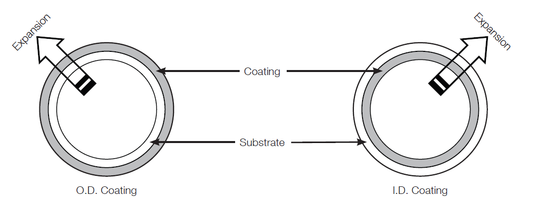
Figure 8: Thermal expansion of parts coated externally and internally.
So, how do we achieve all this required temperature control? Essentially, it’s all about removing thermal energy in a controlled way at the same time we are applying it i.e. balancing the heat flow. Mostly this involves the use of auxiliary cooling in the form of directed compressed air, sometimes liquid carbon dioxide (CO2) and occasionally liquid nitrogen.
Most applications will be adequately cooled via the use of clean, dry, compressed air (remember, we don’t want to contaminate our prepared surface or our coating as it’s being deposited). Cooling jets can either be fixed (see Figure 9) or gun mounted (see Figure 10). In both cases, it is important to control supply pressures, cooling jet sizes and distance to the substrate, as all these factors will affect the heat withdrawal process. Care should also be taken not to allow the cooling stream to impinge on the spray plume as this can have a (in most cases) negative effect on the coating.
The use of fixed siphon cooling jets can be especially beneficial as they can be positioned close to the area being sprayed and can deliver large volumes of air “siphoned” in from the immediate environment.
Gun-mounted cooling jets have the advantage of traveling with the gun so that they can therefore efficiently cool a moving area immediately adjacent to the spray stream. Of course, they can’t deliver as much cooling media as a fixed cooling nozzle.
In particular cases where significant amounts of fine material is generated by the spraying process, gun mounted jets can be positioned so that the cooling media intersects just past the spray distance (see Figure 10). This positioning ensures that the plume is not negatively affected by the cooling, but the surface being coated is cleaned of fine product on either side of the flame as it sweeps over the surface. This can change a “rough as sandpaper” coating to one that is as smooth as a baby’s derriere.
The more energetic the spray process, the more challenges there are to control the temperature regime the coated part experiences. For processes such as HVOF-LF and -GF, there can be often a need to use cryogenic cooling methods. More heat going in, more cooling required to remove it.
Figure 11 shows a Diamond Jet™ HVOF GF system spraying a shaft using gun mounted
CO2 jets. In this case the CO2 is supplied in liquid form. As it exits the nozzles, it changes to a “solid” snow. When this hits the surface, the energy required to transform from solid, to liquid, to gas provides a very efficient method of heat removal.
To properly control the balancing effect between heat absorbed and heat removed, it is good practice to use some sort of temperature measurement device. These can be contact or non-contact systems depending on the type of job being sprayed. In all cases, it makes sense to define and monitor the part temperature profile during the spraying process to ensure no damage is encountered by either the part and/or the coating.
Cooling processes should be regarded as a key process variable as they can have a significant effect on the properties of the coating and the success of the application. As such, care should be taken to record such variables as air pressure, cooling nozzle to work distance, nozzle size, etc., to ensure repeatability.
Hopefully, this article has provided some background on some of the thermal spraying process parameters that are important to consider when aiming for a coating which meets your and the customer’s expectations. There are many parameters which affect the thermal spray process. Manipulation and temperature control are just two more aspects which need to be carefully controlled. My main message is therefore that they should be treated as a process parameter with values and tolerances properly applied. Without this, coating quality can be affected in a ways that are unexpected and quite possibly costly.

Figure 9: Application specific position of siphon air cooling jets.

Figure 10: Setting up focused air-cooling jets.
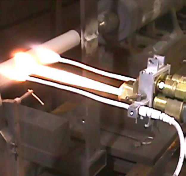
Figure 11: Carbon dioxide cooling jets mounted on a DiamondJet™ HVOF-GF gun.
Dear Friends and Colleagues,
In this article, I hope to provide an overview of those spraying techniques critical to the controlled deposition of a thermally sprayed deposit. Manipulation methods and temperature control techniques can have a significant effect on coating properties and therefore need to be set within defined limits. This article will hopefully provide background on the need for control and the methods used to achieve this.
A look at different spraying techniques as well as the provision of some hints and tips will hopefully be of interest. I know it’s the same message as I have given previously, but I ask you to excuse me for not covering everything, as this is another one of those large subjects in which many people have significant knowledge and also differing opinions.
As before I would like to invite you to join me in the discussions, ask questions, and leave your personal opinion. Also, if there is a related topic you want me to write an overview of, please let me know. I hope it will be interesting to read and I will be more than happy to receive your feedback.
Steve Bomford is a Training and Application Support Manager with Oerlikon Metco in the UK. Steve is passionate about thermal spray and have over the years in many different positions gathered an extensive amount of knowledge abou thermal spray.
© Copyright 2026 OC Oerlikon Management AG
Back to top keyboard_arrow_up